Revit Tutorial – How to create details in drafting views.

__
Subscribe to this channel: https://bit.ly/3VFqR86
Website: https://bit.ly/3VPUnrJ
__
__
Social Media
Instagram: https://bit.ly/3J8l6Io
Personal Instagram: https://bit.ly/3TMWZnD
Pinterest: https://bit.ly/43LlPc1
Houzz: https://bit.ly/3xm04DE
__
__
What’s in my Bag? Check out my KIT!!
https://bit.ly/3PQtFeC
Camera – https://bit.ly/3POwEEH
Tech – https://bit.ly/43I2hFH
Drawing Tools – https://bit.ly/4aE5YOM
__
__
Creating and Organizing Drafting Views for Wall Sections in Revit
Introduction
This tutorial provides a comprehensive guide on creating detailed drafting views for wall sections and plan details in Revit. Drafting views are essential for specifying construction details like wall assemblies, insulation, and resilient channels. This article walks through the process of building these views, from copying grid guides to customizing components and organizing details within the project for clarity.

1. Setting Up a New Drafting View
To start creating detailed drawings, you need to set up a new drafting view with the appropriate scale. This step ensures that all elements are consistent with the overall project and are dimensioned correctly.

Key Steps:
Go to the View tab / Drafting View and create a new view.
Set the scale for the drafting view (e.g., 1 inch = 1 foot).
Copy over grid guides from an existing detail to serve as a layout reference.
This step sets up the framework for your drafting view, ensuring consistency and accuracy across all details.

2. Adding Detail Components: Studs, Gypsum, and Resilient Channels
Once the drafting view is set up, the next step is to add the necessary components. In this example, a 1-hour fire-rated wall with a Sound Transmission Class (STC) rating of 51 is detailed, starting with the gypsum layers and 2×6 studs.

Key Steps:
Use the Annotate / Component tool to insert detail components like gypsum and studs (2×6 nominal size).
Load additional components, such as resilient channels, from the Autodesk family library if they aren’t available by default.
Align the resilient channels with the studs using the Spacebar to flip orientation if needed.
These components form the core of the wall section, ensuring that the detail accurately reflects the construction method.

3. Customizing and Annotating the Detail
The tutorial emphasizes the importance of clearly labeling and dimensioning all components in the drafting view. Break lines are used to indicate where walls extend beyond the detail, and annotations are added for clarity.

Key Steps:
Add break lines to visually break the wall detail where it extends beyond the view.
Use the Text tool to annotate components like the gypsum, resilient channels, and studs.
Include specific dimensions, such as placing resilient channels 16 inches on center, to ensure clarity for contractors.
These annotations provide essential information for construction, making it easier to understand the detail’s intent.

4. Converting Section Details into Plan Details
To provide a complete view of the wall assembly, the section detail is converted into a plan detail by duplicating the drafting view and modifying the orientation.

Key Steps:
Duplicate the drafting view and rename it as a Plan Detail.
Adjust the components to reflect a top-down view, removing elements like baseboards and repositioning the resilient channels.
Use the Component tool to reinsert the resilient channels, ensuring proper alignment with the studs in plan view.
Plan details provide an alternate perspective, offering a clear understanding of the wall assembly’s layout.

5. Organizing Views and Assigning Categories
Once the drafting views are complete, it’s crucial to organize them within the project by assigning categories and design phases. This ensures that details are easy to locate and manage, especially in large projects.

Key Steps:
Assign the drafting view to a category like Walls for clear project organization.
Set the design phase to Construction Drawings to ensure it is categorized correctly in the project browser.
Organizing views ensures that the project remains well-structured and easy to navigate, especially when managing multiple details.

Conclusion
Creating and organizing drafting views in Revit is an essential skill for producing detailed, accurate construction documents. By following these steps, users can efficiently build and customize wall section and plan details, ensuring clarity and precision. Proper organization of these views within the project helps maintain consistency, especially in large-scale architectural or engineering projects.
more insights

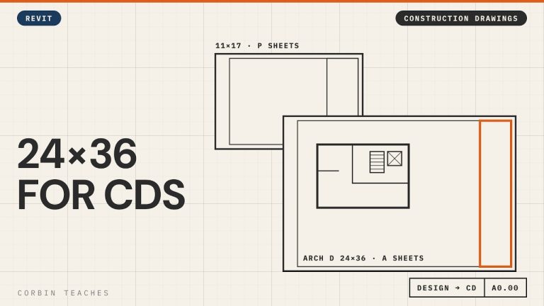
Change the Title Block to Arch D 24×36 — Revit

Change a Revit sheet to an Arch D (24×36) title block and keep your design sheets and construction sheets in the same file. I renumber the 11×17 design sheets from A to P with pyRevit, create new A sheets, then load and edit the Autodesk D title block to 24×36 with a 1″ binding margin.

In this video:
• Two sheet sets in one model: P sheets (11×17 design) and A sheets (Arch D construction)
• Renumber sheets in bulk with pyRevit’s ReValue tool
• New sheet A0 Cover Page
• Load the D 22×34 title block from the Autodesk library and resize it to 24×36
• Margins: 1/2″ all round, 1″ on the binding edge
• Remove the Autodesk logo and consultant boxes, keep the revision schedule
• Save it to your own family library and swap the title block on the sheet

⏱ CHAPTERS
00:00 Design sheets vs construction sheets
00:35 Renumber the design sheets to P
01:07 Bulk renumber with pyRevit ReValue
01:45 New A sheet for the cover page
02:18 Load the Arch D title block
03:12 Resize the title block to 24×36
04:02 Margins and the binding edge
04:34 Remove the logo and consultant boxes
04:51 Save it and swap it on the sheet

▶ DESIGN TO CONSTRUCTION DRAWINGS
Part 2, design, CD and working views: https://youtu.be/g4AHt1J606k
Part 3, revision clouds and issues: https://youtu.be/Y9e53z65nV0

#Revit #RevitTutorial #BIM

━━━━━━━━━━━━━━━━━━━━━━
🔗 FREE & PAID RESOURCES
━━━━━━━━━━━━━━━━━━━━━━
📁 Notion Business OS for Architects (my most popular template):
https://cpd.gumroad.com/l/civaw?utm_source=youtube&utm_medium=description

📁 Free Notion Issue Tracker for Architects:
https://cpd.gumroad.com/l/cjlls?ref=yt-arch-d-title-block

🌐 More Revit tutorials: https://corbinteaches.com

━━━━━━━━━━━━━━━━━━━━━━
CONNECT
━━━━━━━━━━━━━━━━━━━━━━
Subscribe: https://bit.ly/3VFqR86
Instagram: https://bit.ly/3J8l6Io
Architecture work: https://bit.ly/3VPUnrJ

Read more >

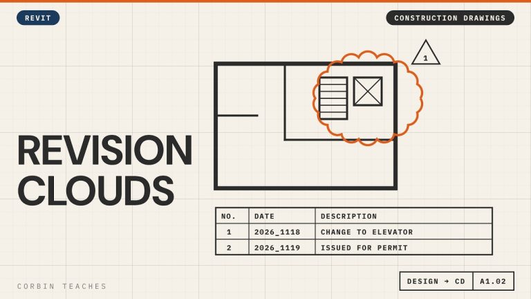
Add Revision Clouds and Issue Sheets for Permit — Revit

Add revision clouds in Revit, make them red, and issue a set for permit without clouding every view. I place a cloud from the Annotate tab, set up the revision in View › Revisions, change the cloud and tag colour in Object Styles, then add an “Issued for Permit” revision to every sheet at once.

In this video:
• When to start using revisions (after design approval)
• Annotate › Revision Cloud, and where it shows up on the title block
• View › Revisions: date, description, Cloud and Tag vs Tag Only, Issued
• Why Issued locks the cloud
• Make clouds and revision tags red: Manage › Object Styles › Annotation Objects (not Line Styles)
• A revision with no cloud: Issued for Permit
• Add it to many sheets at once: select sheets › Revisions on Sheet

⏱ CHAPTERS
00:00 Why use revision schedules
00:56 Draw a revision cloud
01:27 Set up the revision in View › Revisions
02:13 Issued locks the revision
02:30 Make revision clouds red
03:38 Issue a set without clouds
04:23 Add the issue to many sheets at once
05:30 Cloud plus issue on the title block

▶ DESIGN TO CONSTRUCTION DRAWINGS
Part 1, Arch D title block: https://youtu.be/kI_12LX83co
Part 2, design, CD and working views: https://youtu.be/g4AHt1J606k

#Revit #RevitTutorial #BIM

━━━━━━━━━━━━━━━━━━━━━━
🔗 FREE & PAID RESOURCES
━━━━━━━━━━━━━━━━━━━━━━
📁 Notion Business OS for Architects (my most popular template):
https://cpd.gumroad.com/l/civaw?utm_source=youtube&utm_medium=description

📁 Free Notion Issue Tracker for Architects:
https://cpd.gumroad.com/l/cjlls?ref=yt-revision-clouds-issue

🌐 More Revit tutorials: https://corbinteaches.com

━━━━━━━━━━━━━━━━━━━━━━
CONNECT
━━━━━━━━━━━━━━━━━━━━━━
Subscribe: https://bit.ly/3VFqR86
Instagram: https://bit.ly/3J8l6Io
Architecture work: https://bit.ly/3VPUnrJ

Read more >

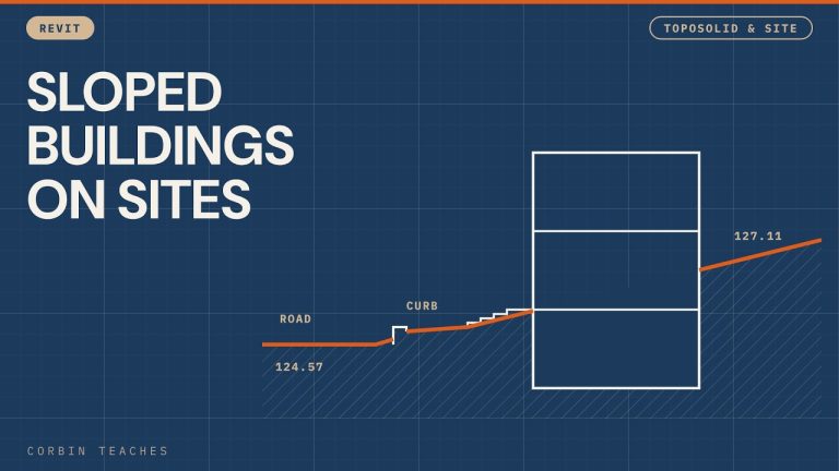
Model a Sloped Site from a PDF Survey — Revit

Model a sloped urban site in Revit, starting from a PDF survey. I import and scale the PDF, build a toposolid from the survey spot elevations (about 2.5 m of fall across the lot), drop the site to a working level with the survey point, then add the road, sidewalk, a custom curb and stairs that meet the grade.

In this video:
• Import the PDF at 300 DPI and scale it with a 10 m dimension (metric survey in an Imperial project)
• Toposolid past the property line so you have context for renderings
• Add Point with Absolute elevations, and switching units to metres while you click points
• Move the survey point and offset the toposolid so the site sits near Level 1
• Let Revit do the math: type =128.4-126.5 in an elevation field
• Quick property lines (and why you should use bearings and distances)
• Sub-divide the road and set it to asphalt, raised slightly above grade
• Sidewalk as a floor with Pick Lines, then shape it to the slope with Modify Sub Elements
• Edit the Thickened Slab Edge profile into a curb with a reveal and rounded edges
• Stairs from the sidewalk up to the floor, with one extra riser so the top tread meets the slab
• A floor as a transition piece between the sidewalk and the stairs
• Environment for Revit: shape a floor to the toposolid

⏱ CHAPTERS
00:00 A site with a 2.5 m grade change
00:39 Import the PDF survey
01:02 Scale the PDF
02:35 Toposolid past the property line
03:19 Add points at absolute elevations
06:10 Bring the site down with the survey point
09:19 Let Revit do the math
10:12 Sketch the property lines
11:12 Sub-divide the road as asphalt
13:42 Sidewalk as a floor
18:08 5″ concrete sidewalk type
19:11 Shape the sidewalk to the grade
21:33 Slab Edge for the curb
22:16 Draw the curb profile
25:27 Load the curb and set the type
28:17 Building set into the slope
29:01 Stairs from grade to the floor
31:01 Transition floor at the stairs
33:45 Environment for Revit: floor to topo

▶ MORE TOPOSOLID & SITE
Sidewalk curb with a custom slab edge: https://youtu.be/lxnMa_H3UMY
Create toposolids and sloping terrain: https://youtu.be/QDorK4ib9vs
Sloped topography and stone steps: https://youtu.be/NbaSLRGHhJw
Property lines and site plan: https://youtu.be/sauTm8wf3Eo
Point cloud to toposolid (Environment plugin): https://youtu.be/Npw_hHhZVYU

#Revit #RevitTutorial #BIM

━━━━━━━━━━━━━━━━━━━━━━
🔗 FREE & PAID RESOURCES
━━━━━━━━━━━━━━━━━━━━━━
📁 Notion Business OS for Architects (my most popular template):
https://cpd.gumroad.com/l/civaw?utm_source=youtube&utm_medium=description

📁 Free Notion Issue Tracker for Architects:
https://cpd.gumroad.com/l/cjlls?ref=yt-sloped-site-pdf-survey

🌐 More Revit tutorials: https://corbinteaches.com

━━━━━━━━━━━━━━━━━━━━━━
CONNECT
━━━━━━━━━━━━━━━━━━━━━━
Subscribe: https://bit.ly/3VFqR86
Instagram: https://bit.ly/3J8l6Io
Architecture work: https://bit.ly/3VPUnrJ

Read more >